|
Basic Transmitter
Workshop for Beginners
You have probably looked
at the basic receiver workshop, well now lets look at the transmission
side of things, First a WARNING if you intend building any of the
transmitters in this workshop, remember that for most transmitting of RF
signals you will need a license for the appropriate band and frequency you intend
transmitting on, fines for ignoring this are heavy and can even result in
a jail sentence, you have been warned (there are some low power exemptions
to this for guidance refer to Ofcom), the body that regulates
all radio transmissions and broadcasting.
That out the way lets make a
start, probably the most important part of a transmitter is the oscillator
that produces the RF Signal (Sometimes referred to as the exiter
stage).
So what exactly is an
Oscillator, well I can explain this best if I tell you to think of
the last time you went to see a group or band, no doubt you will have had
to cover your ears over when the singer got too close to the speaker
system with the microphone and the result was a loud high pitched squeal,
what has happened here is the amplifier has turned into a giant
oscillator, why? because its output has been fed back to its
input, now if you ask the group what's happening they will tell you
its: Feed Back. Exactly and that is just what we need to create, but in a
controlled manner and at an exact frequency, in our case at a radio
frequency, this is two higher frequency for the human ear so you can't
hear it, but the effect is just the same.
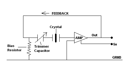
| Lets look
at a basic idea in schematic form, on the right you will see an
amplifier (AMP), the output of which is fed back to its input via a
trimmer capacitor and a crystal, the crystal or resonator is
the device in this circuit controlling the frequency at which the
resultant oscillation takes place, crystals can be bought for a wide
range of frequencies and are very stable of that frequency, they can
be made to shift a very small amount by adjusting the trimmer
capacitor, but will stop oscillating when they reach the maximum +
/_ tolerance, so this gives you an idea of an
oscillator. |
 |
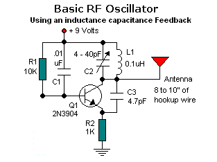 |
As shown on the left it
is possible to replace the crystal with an inductance
capacitance network L1 C2 in the schematic this is similar to
the circuit shown in basic receiver circuits, but this is not a
recommended oscillator as it can drift in frequency and and
suffer instability it is also very hard to tune to the desired
frequency, so the crystal type circuit shown above or similar is by
far the best basic oscillator, never the less we should look at the LC circuit
in more detail to give you a better idea of what we need from an
oscillator, look at the drawing then, Q1 is the amplifier in this
case a transistor, the output is fed back via the transistors 9 volt
supply line though R1 and C1 to the base (or Input) and the
frequency is controlled by L1
C2. |
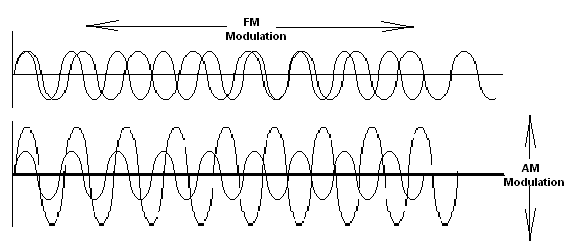
So now we have a very
weak RF signal on a frequency that is controlled by either a crystal or an
LC (Inductance Capacitance) network, this signal can be received as a
carrier on a receiver placed close to it, but it has no way of
adding modulation to it, that is to add an audio signal such as your
own voice that will be heard on the receiver, this is called Modulation
and takes the form of two types: FM modulation(Frequency Modulation)
or AM modulation(Amplitude Modulation) in FM the audio is inserted at the
oscillator stage and causes the frequency to shift, in AM the audio is
inserted later in the transmission process and causes the amplitude of the
carrier to vary, See Block diagrams below AM TX on the left and FM TX
on the right, below that you will see a sign wave of the FM and AM
Modulation, this shows what happens to our waveform when modulated by AM
and FM.
| You can see from
the waveforms on the right the difference between FM and AM
there is one other form of RF Modulated output and this is SSB
(Single Side Band) and this is where one or other of the sine
wave is suppressed, in the transmitter by filters, see the
diagram in the receiver workshop for an example wave form for
this, next we look at the way the signal is amplified many
times before being fed to a suitable
antenna. |
|
| But before we do this lets look at something I
very often get asked how does the RF signal travel through what seems
to be thin air, well ok that's easy take your own voice when you talk to
your friends your voice produces vibrations in the air through your vocal
cords in the voice box, and are picked up by your friends through their
ears, where the vibrations hit a sensitive membrane which vibrates at the
same frequency as those generated by your vocal cords and are turned into
an electrical signal sent to the brain for encoding into an understandable
communication.
Now I am asked well why
can't I hear radio RF signals, well remember what I said about this at the
beginning in the oscillator explanation, RF Signals or
oscillations are at two higher frequency for the human ear, RF
frequencies are well above those produced by your vocal
cords.
And finally why do the signals
fade out after so many miles, well a lot of this can be to do with the
frequency at which the RF signal is being transmitted, but this aside all
signals will eventually run out of steam and become un-receivable, imagine
this if you throw a stone into still water it start with a big splash
which turns into ripples with progressively fade out as they travel across
the water until they can't be seen, the same goes for RF Waves, when they
leave the transmitter antenna they make a big splash, but as they travel
through the air these waves get less and less until they can't be picked
up, that's it, I hope that helps, now back to amplifying our
transmitter output.
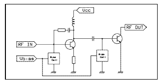 |
First of all then we
need to amplify the RF signal enough to drive the final power output
stage that will send the signal to the antenna, here then is a
simple two transistor RF amplifier that will be enough to give 3 to
5 watts output depending on the transistors used, I will be
following this page with a power RF output stage in another article
soon.
I hope this has been of
use to the less technically minded and given you an insight into how
we get our radio signals into the air around
us. |
<HOME>
|