|
Slim Jim Antenna
Build
As already mentioned elsewhere
on the website, A while ago now I built a new Slim Jim antenna for the
2 Meter band, I last built one of these antenna's back in the mid
80's that version was made of coat hanger wire and very soon corroded and
came off its mounting in a gale, but while it was new it was a very good
antenna and I was well pleased with
it.
While I was browsing the
internet for antenna projects that looked interesting I came across
the old slim jim design, but this time made out of 15mm copper tubing
rather than the coat hanger version, it looked interesting enough to make
me try it out, but could you really get the SWR down on 15mm copper
tubing.
 |
Well only
one way to find out so off to the local plumbers merchants to buy
the bits I needed, copper piping, elbows, and clips, that's it all
you need, I chose to build mine for 2m but they will work on other
bands, they are only a single band antenna though so you have
to build one cut to size for each band you want to use it
on.
Well now my antenna
is now complete and in use, and guess what the SWR is below 1.5 to 1
almost all of the way across the band.
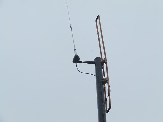
Left is a photo of the antenna
mounted on a piece of 3inch diam UPVC down pipe, along with a dual
band 2/70 antenna I use for 70cm working.
this antenna works so well I thought
I would share the design with you, so set out below are all the
details you need to get started, including the calculation for
length. |
|
FORMULAS
(For
results in inches)
NOTE: Air
gap and element spacing may have to be determined by
some experimentation for various frequencies.
See new info about gap spacing
below.
(Divide
results by 12 for feet)
3/4 wave (longest section = 8415 /
fMHz = inches
1/2 wave section = 5610
/ fMHz = inches
1/4 wave section = 2805
/ fMHz = inches
* 1/4 wave free space = 2953 / fMHz
= inches
*
This is the distance that antenna should
be
from mounting boom, mast or
tower.
Note:
These formulas are believed to be
accurate.
Some trimming or tweaking of
lengths may be needed with YOUR construction!
Slim Jim Metric
Formulas:
(For results in
Centimeters,
multiply results by 100)
213.74
/ fmhz = 3/4 wave overall
length
142.496 / fmhz = 1/2 wave
length
71.248 / fmhz =
1/4 wave length
Feed point = About 10 to 20%
of 1/4 wavelength (+ -
tuning)
75 / fmhz = 1/4 wave
"freespace" in Meters
Note:
These formulas are believed to be accurate. Some trimming
or tweaking of lengths may be
needed with YOUR
construction!
============================================
Some
Examples
2
Meters 146.00mhz
3/4
wave section 8415 divided by 146 =
57.63
inches
1/2 wave section 5610 divided
by 146.00 = 38.42
inches
1/4 wave section 2805
divided by 146.00 =
19.21
inches
1/4 wave freespace 2953
divided by 146.00 =
20.22
inches
Feed point about 10 to 20% of 1/4
wave = 1.9 to
3.84
inches
(+ - tuning)
The
gap would be a guestimate at about 1 1/2 to
2
inches (+
- tuning)
Remember,
the 1/4 wave free space is the distance from the mount
as a
minimum.
============================================================
6
Meters 50.150mhz
8415
/ 50.150mhz = 167.79
inches
5610 / 50.150mhz =
111.8
inches
2805 / 50.150 =
55.93
inches
Gap spacing 10 to 20% of 1/4 wave =
8
inches
(15%)
Free space mounting distance
58.8
inches
============================================
If
you have not got any experience of soldering 15mm copper pipe
don't panic, you will need a blow lamp (gas is
essential), rub the ends of the copper pipe with wire
wool or pan scrubber, apply a small amount of flux to the
clean pipe ends, assemble with a 15mm bend on each corner and
apply heat to each bend until a small amount of solder starts
to appear out of the joint then stop immediately and move to
another corner, at the gap clean 1/4 wave and 1/2 wave ends
and place the two 15mm blank ends to make the inner water
proof and solder as
above. | |
Note:
The Calculations on the left
are example frequencies you must add the frequency you want the
antenna to resonate at.
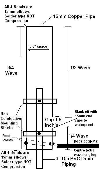
For example take the 2 meter
band, I did my calculation for 145.000 and not 146.00 and my antenna
is built as below.
- 3/4 wave (long
section) 58.034 inches
- 1/2 wave
leg 38.68
inches
- 1/4 wave
leg
20.36 inches
these figures work fine and as
I say my antenna has an SWR of less than 1.5 to 1 across the
band.
Tuning the antenna is easy
enough, connect a good SWR Meter and connect two temporary croc
clips to the inner and outer conductors of the feeder coax (RG58) or
similar, clip these to the connection points shown inner to long leg
screen to 1/4 wave section, move the clips up and down equally on
both sides until an SWR of 1.5 to one or less is found, then remove
the clips and solder the coax to the 15mm tube seal coax end with
silicon sealer and recheck SWR before lifting into
situe.
If your looking for an
interesting project for the summer month's try this out it really
does work well.
Cheers and
beers
Martin
(G8NQN) |
<HOME>
|