 |
-
From Sunny North Lincolnshire uk
-
World Time Clock
|
|
|
|
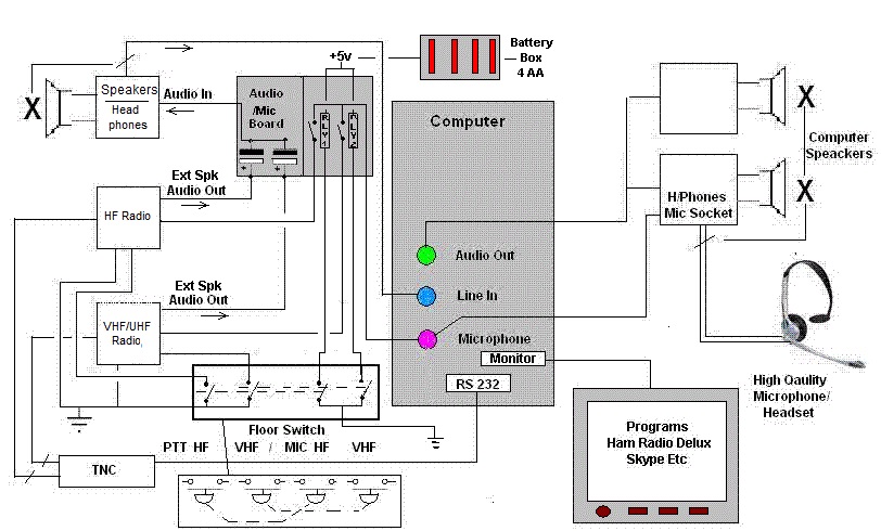
you can see that the audio out from both rigs is taken to a speaker in this case a Kenwood SP-31, this has various tone settings (Useful) and an headphone socket, the audio is taken through a 1500 uF Electrolytic Capacitor from each rig to stop any audio stage crossover, this can be built on a little piece of veroboard to make it more professional, this board will also hold the relay's 1 & 2 which are to connect the headset microphone to the appropriate rig. (Continued Below)
Lets look now at what is happening here, both rigs can be listened to through the Kenwood speaker, next we take a feed from the headphone socket on the speaker to the line in socket on your computer (blue), we then take a feed from the computers audio out socket (Green) to a pair of good quality powered computer speakers which have an headset input (essential). Now you can listen to both rigs through the computers sound card and its speakers or a headset, the reason for this is that you can now tap the audio for programs like ham radio deluxe etc etc, particularly useful for SSTV, FSTV, RTTY, and other such programs, you can also use a program like cool edit pro to record everything from both rigs and save the recording in Mp3 format, next we add a TNC controller to the computers RS 232 socket, this allows programs like Ham Radio Deluxe to control the rigs output and do all the other things these wonderful programs can do. It is of cause a fact that we don't want our rigs computer controlled all the time, so we add another little bit of circuit to this system, a high quality microphone headset and a foot operated switch to operate the PTT lines on each rig, and the microphone relays, output from the speakers microphone connection is then taken to the mic in on the computer (Pink), note now that the computer speakers are muted and you can hear both rigs in the headphones, so now we have the audio from the rigs in our headphones and a microphone to the computer, next we split the microphone cable on its way to the computer mic socket (Green) or use a 3.5mm piggy back connector, and take a feed to the switching relay's, you will see from the diagram that when we press the PTT floor switch for each rig this also feeds our headset mic to the appropriate rig via the relay 1 & 2 switched by a second pole on the floor switch, we do this to stop the microphone level being pulled low by being connected to too many device inputs, but you will need to use screened cable throughout on this part of the circuit or you will get RF feeding into the microphone circuit, I would also recommend throwing in a few Ferrite Beads into the whole circuit for good measure. The beauty of this circuit is that you can use programs like Skype, without making any further changes as its all connected through the computers sound card. Thats about it, I am in the process of making refinements to this circuit but so far its working very well indeed, but there's a few bits I want to change yet. 73's Martin (G8NQN)
|