|
Radio Receiver
Basics for Beginners
How it all works
for those new to the workings of radio receivers and potential
new radio ham's.
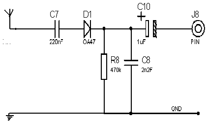
- Lets start out with a basic crystal set figure (A), by
connecting an antenna and ground, strong nearby radio signals will be
picked up and by connecting an ear piece between J8 and ground they will
appear as audio signals,
- D1 being the
detector Diode.
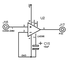
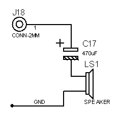
By adding an audio stage (B)
and amplifying this audio signal it can be made to drive a small
speaker (C).
|
|
However this is fine as an
experiment or to get the basic idea of receiving radio signals, but is no
good as a working radio because it is non selective of frequency and will
pick up all the local strong RF signals as a jumble, to be able to tune
the receiver to one of the signals filtering out the ones we don't want we
need to add a tuned circuit, this is a coil of wire (L1) below (left),
made to resonate at the desired frequency and finely tuned by a variable
capacitor (C1) below (left).
|

The circuit (Right)
works well But there are still other factors to take into account
with this receiver, like frequency stability etc, which can be
improved.
So next we look at
a design called a super heterodyne receiver, which takes care of
these problems and is in use to this day, this is how it works,
following the amplification of the RF signal it
is fed to a mixer stage where it is mixed with another
frequency from a local oscillator after which they are passed
through an intermediate frequency stage called the IF stage, before
being amplified in an audio stage and fed to the speaker,
An FM receiver block
diagram is shown below. |
|
Now you can see
that our little experiment is starting to take the shape of a
tuneable radio capable of receiving RF signals and
turning them into an audio signal that we can listen
too.
But these RF
signals are still very weak and for us to be able to receive
distant stations they will need to be amplified many times
over, Below then we have a basic receiver front end with a
single transistor RF amplifier stage, ferrite rod antenna
and twin ganged tuning capacitor followed by a diode detector
which can then be fed to an audio
stage, |

|

|
|
In modern receivers all the RF
amplification and the local mixer oscillator stage are all in one
single chip, as shown below, although this is only again a basic circuit
it gives you the idea. |
|
|

|
|
Lets Examine the
circuit on the left then, in this is a single chip mixer and
local oscillator NE612, pin 1 is RF in from the antenna, this
is tuned by Co and C10 where it is also mixed with the local
oscillator frequency on pins 5 & 7 via c1 &
c2, and local oscillator tuned circuit, this being
transformer Lo.
The output to the
IF Filter primary is on pins 4 & 5, and the centre tap of
the secondary in the IF Filter is then taken via the Detector
diode AA121, to the audio stage via the bias network C8 R1 and
capacitor C4 to a volume control P 50k log pot, this is then
fed into the audio amplifier IC LM386 on pin 2, the output
from the audio chip on pin 6 then goes to the 8 ohm speaker
via C10, with C9 and R2 providing the output
Bias.
This is a simple
little 2 chip receiver which is ideal for beginners to build,
it will give you the motivation to take on larger projects,
and will be greatly satisfying when its complete and
working.
Again most of the
components for this can be obtained from Electronics supply
shops like Maplin, RS, etc.
Good
luck. |
| |
|
Now lets move on to
a more serious side of things.
Lets look at the IF strip of a
Heterodyne receiver, this follows on from the mixer stage and is
tuned to a frequency that is derived from the input frequency mixed
with the local oscillator frequency (see below) if the IF
strip is not tuned correctly the stage will give poor reception
results, that is why they have ferrite tuning slugs (D), never try to
adjust these without the correct tools, breaking a tuning slug inside the
transformer can be the end of the radio, these transformers are wound for
individual sets depending on the local oscillator frequency, and very
difficult to get hold of or replace, and once broken cannot be removed
easily, always use a plastic tuning stick (Never use a
screwdriver), plastic tuners can be obtained from most
electronics suppliers, such as Maplin, RS Spares, CPC, etc.(More on tuning
the IF stage later). |
 |
Heterodyne receiver
continued
Below you can see how the IF
frequency is determined, you are tuned to 6.00Mhz and the local oscillator
is running at 5Mhz this results in a 1Mhz frequency into the IF
strip.
|
|
A Couple more Block Diagram's
for you then, below is an AM or (Amplitude Modulation)
receiver. |
 |
|
| And below is
an SSB Receiver block diagram, this receiver is used in short wave
radio's, where one side of the carrier is suppressed to form (Single Side
Band), you can filter out either the lower or upper side band resulting in
USB or LSB, (See Diagram Below Right), the signal is then mixed with
a BFO (Beat Frequency Oscillator) signal, this resolves the missing side
band at the product detector stage, by finely tuning the BFO the missing
side band is added back in, before the signal is fed
to the audio stage, making a listen-able signal, again this is too much to
explain fully in this article, but there are reference books on this
subject available. |
|
|
Just one last
thing we must look at now, A phase lock loop
circuit
History of the phase
lock loop goes back
to 1932, when British researchers developed an alternative to
Edwin
Armstrong's
super heterodyne
receiver, (The
Homo-dyne) In the homo-dyne system, a local oscillator was tuned to the
desired input frequency and multiplied with the input signal. The
resulting output signal included the original audio modulation
information. The intent was to develop an alternative receiver
circuit that required fewer tuned circuits than the super heterodyne
receiver. Since the local oscillator rapidly drifted in frequency,
an automatic correction signal was applied back to the oscillator,
maintaining it in the same phase and frequency as the desired
signal (Phase Lock Loop). The Phase lock Loop circuit
keeps the receiver frequency very stable and free from drift,
with phase locked loop circuits now built into one single chip, they
are common place in modern radio & television receiver
design. |

Here
is a block diagram explaining the principle of the phase lock loop,
it
| |
| Now as promised
lets look at tuning the IF Strip |
|
|
|
Firstly don't forget the
warning given above always use the proper trimming tool and never
ever use a screwdriver to trim the ferrite cores, this is the theory
of tuning then, we will apply a steady RF signal of constant
strength to the front end of the receiver and then insert a
micro-volt meter after the IF stage but before the audio stage,
starting with the final coil on the IF stage, carefully turn
the ferrite core until the meter peaks at it highest level, now move
back to the next If transformer and do the same, and lastly go to
the first IF transformer in the IF strip and tune that until the
meter peaks, finally run down the strip again double checking for
the peak meter reading, if the cores are lose in there thread and
can be wobbled about, seal with a small amount of candle wax, your
done.
Just another warning
before you embark on this process, make sure you have correctly
identified the I.F transformers, there will be other tuned circuit
transformers that look the same such as the local oscillator
coil, and main front end tuning coils etc, de-tuning these by
mistake will cause you a lot of hard work, and will need
specialist equipment like an oscilloscope to get the radio working
again, in some sets the I.F transformers are dabbed with a paint
colour like yellow which helps identify them, likewise the local
oscillator coil will also be marked usually with a dab of red paint,
very useful for the engineer.
The photo below shows
the signal generator and meter for tuning
purposes.

|
|
HOME
|
|
|
| |